machinist@lists.ibiblio.org
Subject: Machinist
List archive
[machinist] Milling small precise angles - [setting compound for turning tapers - using sine bar to set compound]
- From: Lawrence London <lfljvenaura@gmail.com>
- To: machinist@lists.ibiblio.org, Lawrence London <lfljvenaura@gmail.com>, "Lawrence F. London, Jr." <lflj@bellsouth.net>
- Subject: [machinist] Milling small precise angles - [setting compound for turning tapers - using sine bar to set compound]
- Date: Sat, 16 Nov 2013 21:39:03 -0500
http://www.practicalmachinist.com/vb/general/milling-small-precise-angles-275209/
Thread: Milling small precise angles
-
 Milling small precise angles
I am trying to design a template/tool to aid a quick setup of the compound on my lathe. I intend to use it for setting up very small but precise angles when cutting Morse tapers. To do this by trial and error using a dial indicator takes forever. I figure using a flat steel plate as a guide with one side at 90 degrees -1.4306 degrees = 88.5604 degrees (Morse #2 taper). I could then set the compound visavi the cross slide quickly at the precise angle. My problem is that I don't know how to set up and holding the work piece on the milling machine to get the precise result I want. I have a sine bar but I haven't figured out how it could be used in this particular case. I am looking forward to any suggestions.
-
 Doesn't take forever if you put a 1" or 2" plunger indicator on the bed ways contacting the front of the saddle and a another 1/2" or so plunger at right angles sitting on the bed but in contact with the compound ways or side of the compound if it is accurately made as mine is. Move the saddle 1" (or 2")and the indicator in contact with the compound slide should slide along and move the corresponding amount to make your taper. Figure your expected movement in the compound by trigging your taper angle. Adjust angle of compound until it is right. Takes a little fiddling at first to get your compound indicator set at the right height. But once you figure that out it is pretty quick and easy. I just did this for a Morse2 and also for a 3/12 taper for my surface grinder. With just a little care you can get within a 1/2 thou or better over an inch. I will be grinding my tapers after hardening the pieces. So I did not fit them better than that. But by using some Dykem or Sharpie ink you could fine adjust to a "perfect" fit.I am trying to design a template/tool to aid a quick setup of the compound on my lathe. I intend to use it for setting up very small but precise angles when cutting Morse tapers. To do this by trial and error using a dial indicator takes forever. I figure using a flat steel plate as a guide with one side at 90 degrees -1.4306 degrees = 88.5604 degrees (Morse #2 taper). I could then set the compound visavi the cross slide quickly at the precise angle. My problem is that I don't know how to set up and holding the work piece on the milling machine to get the precise result I want. I have a sine bar but I haven't figured out how it could be used in this particular case. I am looking forward to any suggestions.
I would not fool with the template myself.
Denis -

In my 50+ years of cutting tapers on lathes I have found no way to reduce fiddle time, even if you are using a taper attachment. You cannot believe the position of a witness mark on a TA, let alone a compound. I always chuck up a standard, then mount a dial indicator on the compound and adjust for 0. No way to avoid it.
-

If you make one side of your compound parrallel with the movement you can clamp on a sinebar with some rubber bands to it
Then set the sinebar to the correct angle and indicate the compound to zero
Peter from hollandJohn Welden and hanermo like this. -

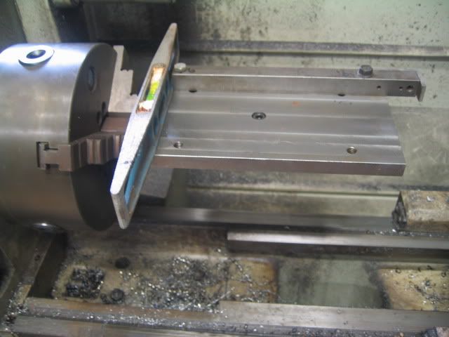
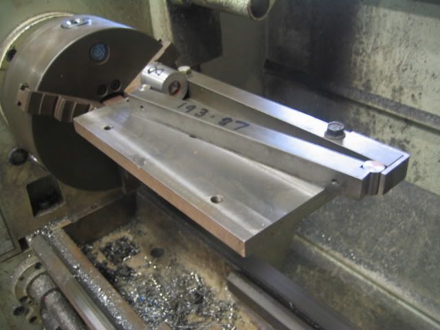
A few years ago on here there was mention of a chuck mounted sine bar for setting compound angles, which I thought was a very clever idea. I've made one from bits and pieces and I find it to be very useful in setting up to turn morse tapers, ER tapers etc.
Shaft, plate and fence, the RH end of the fence is adjustable.

The sine bar is about 50% longer than the standard 5" item. Rather than use blocks to set the sine bar I use pieces of round turned to the required diameter.

-
 Amazing to me that you have a chuck that is accurate enough to hold your standard spot on. I have decent chucks but there is always some runout. Even with a 4-jaw or set-true arrangement, it is easy enough to get one portion of a straight bar to run true but but somewhere else along its length it is not. I have placed a standard, when available, between centers and come closer to dead nuts. (Problem is that a convenient standard with accurate center holes is often not available.) The centers work as long as your tailstock is on the money. For me, the two-indicator method has gotten around those sources of error and produced the best fitting tapers straight off the lathe. I think that is because it measures what you really want to happen---movement of compound vs. movement along the bed ways. I agree that if I really want "perfect," it is still necessary to slightly tweak the compound setting using some form of dye/ink and a taper to test against. Actually I can often see where the cut piece shines up on the minuscule crests of the cut if I twist the piece in a socket and don't need the ink. This same "shining up" can be seen on any taper that has been used for a while. Where it comes in contact has a slightly different light pattern on its surface due to wear against the socket.In my 50+ years of cutting tapers on lathes I have found no way to reduce fiddle time, even if you are using a taper attachment. You cannot believe the position of a witness mark on a TA, let alone a compound. I always chuck up a standard, then mount a dial indicator on the compound and adjust for 0. No way to avoid it.
Denis -
-
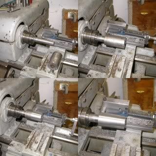
 Another variation of this method that I have used is to place a piece of round bar in the chuck. (Using one of generous diameter, as shown in John's pictures, reduces potential error in determining the up/down contact point for the indicator) Turn it accurately so there is no taper or at least so that it has two equal diameters at two known points (like a test bar) and then use an indicator on the compound. Figure the expected compound movement for a given taper. That gets rid of the inevitable chuck runout and lets you measure taper movement of the compound against a true reference.
Denis -
11-15-2013, 12:02 PM #9
- Join Date
- Sep 2004
- Location
- south SF Bay area, California
- Posts
- 1,269

dgfoster --
bob ward's use of a pivoting fence -- which would be trammed to parallel the lathe bedways, after the spindle is rotated to "level" the baseplate -- effectively takes the fixture chucking error out of the system.
(Do note that I used the term "level" loosely in the above sentence, to mean that the baseplate plane is adjusted to be parallel to the cross-slide movement.)
John -
 Gee, not saying that the ways I suggested are the ONLY ways to do it. Just saying that these methods have been relatively convenient and effective for me---not perfect maybe but good. I hope there will be even more options posted. Love to see them. I thought the sine bar method suggested was cool and a creative way to avoid chucking errors. I think John's method was great. I was simply trying to suggest ways of using common tools to avoid chucking errors in general.dgfoster --
bob ward's use of a pivoting fence -- which would be trammed to parallel the lathe bedways, after the spindle is rotated to "level" the baseplate -- effectively takes the fixture chucking error out of the system.
(Do note that I used the term "level" loosely in the above sentence, to mean that the baseplate plane is adjusted to be parallel to the cross-slide movement.)
John -

You could turn a two-ended Morse taper. Put one end into your spindle, zero out cross-way to the other end, and go.
Keep in mind that for accurate work, you'd have a female MT gage ring, and would blue and scape your work in to that gage. If you're lathe is not spot-on (scraped-in or ground ways), the nice zeroed-out cross-way can move a lttle under pressure from the cutting tool. Even if it's not, cutting an accurate, finished taper with the lathe is going to be very difficult. -
11-15-2013, 02:52 PM #12
- Join Date
- Sep 2004
- Location
- south SF Bay area, California
- Posts
- 1,269

dgfoster --
I'm "getting a vibe" that you think I was critical of you and/or your method. I did not intend to be critical in any way, but apparently misinterpreted your post #6 as suggesting that chucking errors limited the practicality of bob ward's fixture.
Sorry 'bout that.
John -

John,
We're fine! I reread your comment and see now that you were simply pointing out the benefit of Bob's method. I guess when I read your post the first time, since it was directed specifically to me, I incorrectly thought that you intended to correct my perceived oversight or discounting of his fixture. Discounting his system certainly was not the intention of my posts. My only desire was to suggest relatively useful methods not requiring anything more than a DTI or two.
Communication is a tricky business and electronic communication which is absent intonation and body language can easily produce inaccurate vibes with unfortunate results that we see here all too often. Thank you for caring enough to clarify this (and not ripping into me!).
Denis
dgfoster --
I'm "getting a vibe" that you think I was critical of you and/or your method. I did not intend to be critical in any way, but apparently misinterpreted your post #6 as suggesting that chucking errors limited the practicality of bob ward's fixture.
Sorry 'bout that.
John -

Peter, I tried something along these lines but I don't have, nor can I find, gage blocks thin enough to give me a 1.43 degree angle (MT #2) using a 5" sine bar. That's why I was thinking about milling a template to put on the saddle and against the compound.
-
-

If my math is corrrect, that would be a 0.12477808627 bar or gage block. For practical purposes, a .1250 gage pin
that costs 3 dollars from McM would do the trick. Or put it in the lathe and polish off the .0002 if you want to try to come that close.
Denis -

Another option would be to simply make your own block. See post 25 Asking advice on flat lapping custom gage block by hand. Book/video recommendations.
I think the practical solution would be to simply turn a small pin to just over size and then use fine wet and dry paper to get it as close to size as you might need and be able to measure. Then stick it in your sine bar as suggested above if that is the path you want to follow.
No matter how carefully you make your setup, because your lathe will not likely cut perfectly as setup, you will still have to make the last couple of tweaks based on a test fit of the taper you cut. Let us know how you come out.
Denis -
-

That might be solved by putting gauge block stacks under both ends of the sine bar. That is, make up say 0.3248 (if that's feasible) under one end and 0.200 under the other to get into a range you can work with.
-
11-16-2013, 07:45 PM #20
- Join Date
- Feb 2005
- Location
- Owl's Head, Maine
- Posts
- 1,195
- [machinist] Milling small precise angles - [setting compound for turning tapers - using sine bar to set compound], Lawrence London, 11/16/2013
Archive powered by MHonArc 2.6.24.
 Reply
Reply

